



- Home
- Blog
- Technical Articles
- Horizontal vs. Vertical Rotary Table: Which One Should You Choose?
Horizontal vs. Vertical Rotary Table: Which One Should You Choose?
A Complete Guide to CNC 4th-Axis and 5-Axis Machining Upgrades
In CNC multi-axis machining, a rotary table plays a key role in improving machining efficiency, part accessibility, and machining flexibility. The two most common configurations are the horizontal rotary table and the vertical rotary table. Both types can support 4-axis and 5-axis CNC machining, but they differ significantly in load-bearing structure, chip evacuation, workholding method, machine footprint, and suitable applications. Choosing the right rotary table configuration not only improves machining stability, but also helps optimize production efficiency and long-term manufacturing costs.
1. Key Differences Between Horizontal and Vertical Rotary Tables
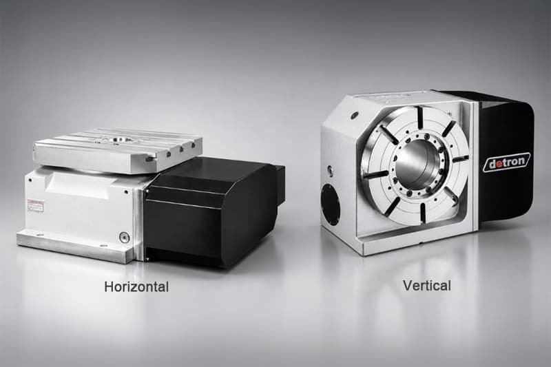
In CNC machine tools and indexing table applications, the terms “horizontal” and “vertical” are defined by the table face orientation and the direction of the rotary axis:
- Vertical Rotary Table:
A vertical rotary table has a table face positioned upright, with the rotary axis parallel to the ground, such as an A-axis or B-axis configuration. The workpiece is clamped onto the vertical face of the table. Because gravity acts downward on the workpiece, it creates a cantilever bending moment on the spindle.
Vertical rotary tables are commonly used as an external 4th-axis rotary table on a vertical machining center, also known as a VMC. - Horizontal Rotary Table:
A horizontal rotary table has a table face positioned upward, with the rotary axis perpendicular to the ground, such as a C-axis or the B-axis of a horizontal machining center. The weight of the workpiece and fixture is directed downward along the axis and supported by the thrust bearing surface.
This structure offers excellent load-bearing capacity and is commonly integrated into horizontal machining centers, also known as HMCs, or large gantry-type machining systems.
1.1 Mechanical Performance Comparison
| Evaluation Item | Vertical Rotary Table | Horizontal Rotary Table |
|---|---|---|
| Table orientation and axis direction | Table face is upright; rotary axis is horizontal. | Table face is upward; rotary axis is vertical. |
| Gravity and load-bearing mechanism | Workpiece weight creates a cantilever moment and radial shear force on the spindle. Long or heavy parts often require a tailstock or external support to prevent spindle deflection. | Gravity acts directly on the thrust bearing surface. This allows high load capacity, stable center-of-gravity distribution, and no cantilever sagging issue. |
| Chip evacuation | Since the cutting surface is vertical, chips naturally fall away from the machining zone. This reduces chip accumulation, re-cutting, and tool interference. | If paired with a vertical spindle, chips may accumulate in grooves or pockets. However, in an HMC with a horizontal spindle, chip removal is highly efficient when machining the sides of tombstone-mounted workpieces. |
| Spindle and bearing rigidity | Requires high moment rigidity and strong brake clamping torque to resist eccentric cutting forces. | The thrust bearing mainly supports vertical axial loads, offering excellent resistance to gravity-induced deformation and heavy cutting pressure. |
| Workholding and alignment | Heavy workpieces may require crane assistance, locating pins, or careful compensation for gravity sag during alignment. | Workpieces can be placed directly on the table face. Gravity helps the part naturally seat against the reference surface, making alignment and clamping faster and more intuitive. |
2. Choosing the Right Rotary Table Based on Workpiece Geometry
The shape of the workpiece, weight distribution, length-to-diameter ratio, and machining features are the most important factors when choosing between a vertical and horizontal rotary table.
2.1 Typical Workpieces for a Vertical Rotary Table
- Long shafts, camshafts, drive shafts, and crankshafts:
Slender shaft-type components with a high length-to-diameter ratio should be supported along a horizontal axis. One end is clamped on the vertical table face, while the other end is supported by a tailstock center. This setup helps maintain radial runout accuracy and roundness during high-speed rotation. - Cylindrical slotting, helical grooves, and multi-angle indexing parts:
For components such as rollers, spline shafts, and gear shafts, a vertical rotary table allows the cutting tool to approach the outer diameter at an optimal feed angle. This is especially beneficial for circumferential milling, helical groove machining, and multi-angle indexing operations. - Multi-face machining of small to medium-sized components:
By rotating the workpiece 90 ∘ , 180 ∘ , or 270 ∘, a vertical rotary table enables machining of three to four side features in a single setup. This reduces repeated clamping, shortens setup time, and improves dimensional consistency.
2.2 Typical Workpieces for a Horizontal Rotary Table
- Large-diameter heavy discs, gear blanks, and flanges:
Large flanges, bearing rings, wind power gears, and other heavy disc-shaped parts are ideal for horizontal rotary tables. When the workpiece is placed flat on the upward-facing table, its weight is evenly distributed across the thrust bearing. This avoids cantilever deformation caused by eccentric loading. - Multi-station box-type components with tombstone fixtures:
A horizontal rotary table is highly effective when paired with a tombstone fixture. Multiple valve bodies, engine blocks, or small precision components can be mounted on a single fixture. With continuous 360 ∘ rotary indexing, manufacturers can achieve high productivity and reduced idle time. - Large box-type components requiring top and side machining:
Heavy machine housings, pump bodies, and structural parts can be placed flat on a horizontal rotary table. The rotary table indexes the workpiece toward the spindle, allowing stable multi-directional machining. Because the center of gravity remains low and stable, this configuration provides excellent vibration resistance and heavy-cutting rigidity.
3. Industry Applications and CAPEX / OPEX Analysis
Introducing a CNC rotary table is not only a matter of equipment purchase cost, also known as CAPEX. It also affects factory layout, fixture expandability, automation planning, and long-term operating expenses, also known as OPEX.
3.1 Rotary Table Applications by Industry
| Industry | Common Rotary Table Configuration | Key Advantages and Investment Benefits |
|---|---|---|
| General machinery and automotive parts | Vertical rotary table on VMC with tailstock | Flexible investment. Existing vertical machining centers can be upgraded with a 4th axis at a lower cost, typically around 15 to 25 of the machine cost. This setup requires a smaller footprint and is suitable for high-mix, low-volume production. |
| Automotive powertrain and mass production lines | Built-in horizontal rotary table on HMC with tombstone fixture | High productivity. With an automatic pallet changer and horizontal spindle, multiple stations can be machined with minimal downtime. This configuration supports high spindle utilization and reduced loading interruptions. |
| Aerospace casings and energy valves | Heavy-duty horizontal rotary table | Superior heavy-load rigidity. Large titanium alloy, high-temperature alloy, and heavy casing components can be clamped securely, allowing the system to withstand high cutting torque and heavy workpiece loads. |
| Semiconductor components and precision molds | Zero-backlash direct-drive rotary table | Ultra-high precision. Direct-drive rotary tables provide excellent surface finish and arc-second-level indexing accuracy, while eliminating backlash and wear issues commonly associated with traditional worm gear systems. |
3.2 Machine Footprint and Investment Cost Evaluation
- Equipment investment cost: CAPEX:
From an investment perspective, a vertical rotary table is often installed as an external 4th-axis unit on an existing vertical machining center. The initial investment is lower and typically accounts for about 15 to 25 of the machine cost, making it suitable for production lines with flexible budgets.
A horizontal rotary table is more commonly integrated into a high-end horizontal machining center or large 5-axis machining system. In many cases, the total machine investment can be more than twice that of a vertical machining center setup. - Factory footprint:
A vertical rotary table combined with a VMC requires less floor space and offers greater layout flexibility. In contrast, a horizontal rotary table integrated with a large HMC and pallet exchange system may require 40 to 60 more floor space. Factory column spacing, chip conveyor layout, and automation routes must be carefully planned. - Operating cost and cutting efficiency: OPEX:
For mass production, a horizontal rotary table with tombstone fixtures delivers high machine utilization and fewer loading interruptions. This makes it highly efficient for automated or semi-automated production lines.
A vertical rotary table may require more manual loading, alignment, and adjustment. However, it responds faster in high-mix, low-volume production environments, especially when frequent job changes are required.。
4. Four-Step Selection Guide for CNC Rotary Tables
When evaluating the right rotary table configuration, engineering teams can follow the four-step decision process below:
Step 1: Check the workpiece geometry and length-to-diameter ratio
- If the workpiece is a long, slender shaft, spline shaft, or drive shaft with a high length-to-diameter ratio, a vertical rotary table with tailstock support is usually the preferred choice.
- If the workpiece is a large-diameter disc, flat flange, or extremely heavy box-type component, a horizontal rotary table is generally the better option.
Step 2: Evaluate the clamping method and fixture structure
- If the production process requires a multi-face tombstone fixture for high-volume machining, a horizontal rotary table is the more suitable choice.
- If the part requires two-end support, continuous circumferential machining, or helical milling, a vertical rotary table is usually more practical.
Step 3: Consider chip evacuation and dynamic rigidity
- For parts where chip accumulation is a concern, a vertical rotary table offers better natural chip evacuation because the cutting surface is upright and chips fall away from the machining zone.
- For oversized and heavy workpieces requiring heavy cutting, a horizontal rotary table provides stronger vibration resistance because the thrust bearing directly supports the downward load.
Step 4: Match the configuration with production budget and machine compatibility
- For manufacturers looking to upgrade existing machines at a lower cost, add a 4th axis, support prototyping, or handle high-mix, low-volume production, an external vertical rotary table is often the most economical choice.
- For highly automated, high-volume, and unmanned production lines, an HMC with a built-in horizontal rotary table and pallet exchange system provides higher long-term production efficiency.
Put Every Workpiece on the Right Machine
In real-world production, many precision machining companies adopt a hybrid configuration. A vertical rotary table is used for standard parts, shaft components, and flexible batch production, while a horizontal rotary table is dedicated to complex box-type parts, heavy cutting, and high-volume machining.
Choosing the right rotary table orientation can significantly improve machining efficiency, accuracy, process stability, and overall cost structure.
If you are still unsure which rotary table configuration best fits your part geometry, tolerance requirements, and existing machine specifications, contact Detron Machine Co., Ltd. Our technical engineering team can provide a professional evaluation and help you build a stable, high-performance 4-axis or 5-axis machining solution.