



Smart Control & AIoT Solutions for CNC Rotary Table
The Digital Brain Driving Smart Manufacturing: detron Smart Control & AIoT Solutions
In the era of Industry 4.0, precision machining can no longer rely solely on hardware rigidity; it requires a "digital brain" equipped with data perception and independent computing capabilities. Breaking beyond the boundaries of traditional components, detron introduces exclusive Smart Control and AIoT solutions tailored specifically for rotary tables. These advanced innovations assist factories in seamlessly executing their digital transformation, maximizing the ultimate potential of their production equipment.
detron's smart control ecosystem is built upon two core pillars. The first is the AIoT Smart Box, a powerful platform for monitoring equipment status. Utilizing built-in sensors and an Internet of Things (IoT) communication architecture, the Smart Box collects critical operational data from the rotary table in real time, enabling precise predictive maintenance. Facility managers can proactively detect potential component wear and system anomalies, drastically mitigating the massive financial losses associated with unexpected downtime. This ensures that production lines maintain an optimal utilization rate of nearly 100%, comprehensively elevating overall production management efficiency.
The second pillar is the SAC Single-Axis Controller, designed for machining facilities that demand extreme flexibility or need to upgrade legacy machinery. When an existing CNC machining center lacks an available servo axis interface, the SAC provides a fully independent control solution. It is compatible with the vast majority of mainstream machine controllers on the market. Without the need for complex and costly system retrofitting, precise indexing control can be achieved through a simple signal handshake (such as an M-Code). With its intuitive and user-friendly interface, the SAC allows older equipment to instantly acquire multi-sided machining capabilities at the lowest possible investment threshold.
The detron Smart Control Series perfectly encapsulates the immense value of software and hardware integration. Whether you are leveraging data analysis to extend hardware lifespans or utilizing independent controllers to flexibly upgrade your production lines, detron is your most capable partner in driving down maintenance costs and building a 24-hour unmanned smart factory.
SCHEMATIC DIAGRAM OF ROTARY TABLE AND CNC SINGLE AXIS CONTROLLER
Schematic Diagram Of Rotary Table And Single Axis Controller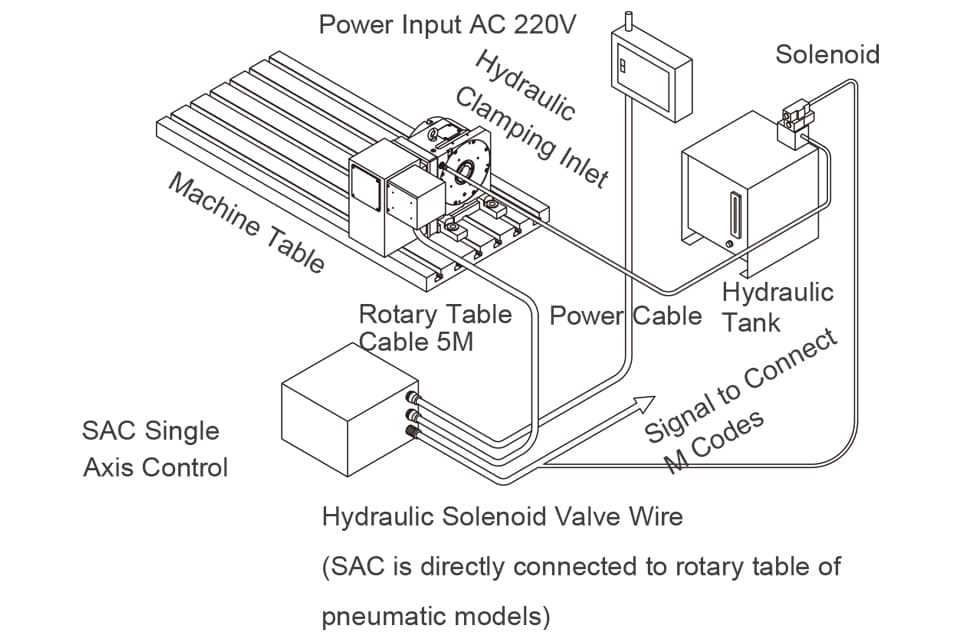
SAC Series- Single Axis Control
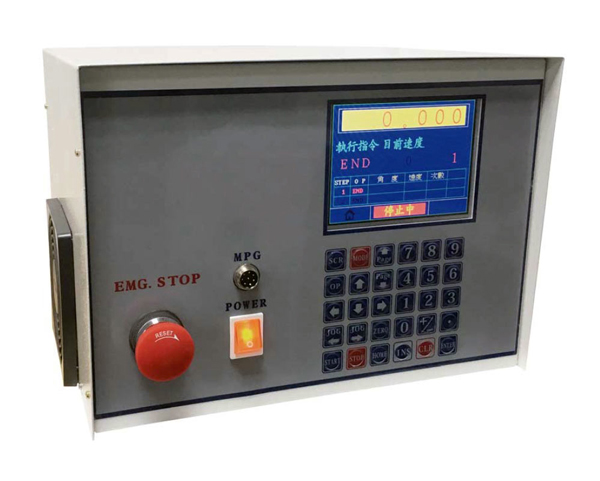
- For machine NC without 4th axis function, SAC provide signals to allow indexing application (no simultaneous function available).
- Programs of rotary table can be directly input through SAC and allow machine NC M code command.
- Compatible with any brand of NC control.