



- Home
- Blog
- Technical Articles
- Principles of Multi-Axis Machining: How to Control Rotary Axes with G-Code
Principles of Multi-Axis Machining: How to Control Rotary Axes with G-Code
As five-axis and multi-axis machining become increasingly common, rotary axis control is no longer just an advanced option—it has become a key factor in improving machining efficiency, accuracy, and process stability. For manufacturing engineers, machining quality depends not only on the machine tool itself, but also on a correct understanding of coordinate systems, accurate G-code programming, and reliable toolpath control through CAM software.
If the program is incorrect, the result may be machining deviation, tool interference, or even a serious machine collision—directly affecting yield, productivity, and production cost.
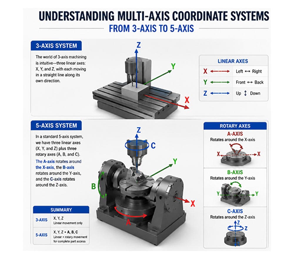
Understanding Multi-Axis Coordinate Systems: From 3-Axis to 5-Axis Machining
In conventional 3-axis machining, the concept is relatively straightforward. The machine moves along three linear axes: X, Y, and Z. Each axis performs linear motion in its respective direction.
Once rotary axes are introduced, the machining space becomes three-dimensional and far more flexible.
In a standard five-axis machining system, the machine includes three linear axes—X, Y, and Z—plus rotary axes A, B, and C:
The A-axis rotates around the X-axis
The B-axis rotates around the Y-axis
The C-axis rotates around the Z-axis
(AI-generated image)
Depending on the machine configuration, such as a trunnion-type or rotary table structure like the detron GFA Series, the combination of linear and rotary axes may vary. However, the fundamental principle remains the same: the CNC controller coordinates linear and rotary motion to maintain the correct tool position and cutting angle.
The key to understanding multi-axis machining is establishing the correct reference coordinate system. If the coordinate system defined in the CAM software does not match the actual machine coordinate system, even a perfectly generated G-code program may produce completely incorrect machining results.
How Multi-Axis Interpolation Works: How G-Code Drives Rotary Axis Motion
A. The Mechanism of Multi-Axis Synchronous Motion
Multi-axis machining is essentially the synchronized interpolation of linear axes X/Y/Z and rotary axes A/B/C. The CNC controller executes this motion through four major steps:
1. G-Code Interpretation
The CAM system outputs an NC program that includes rotary axis angle commands.
The CNC controller reads and interprets the following information:
- A/B/C rotary axis coordinates
- Feedrate F commands
- Interpolation mode
- Absolute or incremental positioning
- Linear or circular motion commands
This is the first step in converting programmed toolpaths into actual machine motion.
2. Real-Time Multi-Axis Interpolation
During multi-axis machining, the controller calculates how each linear and rotary axis should move simultaneously. Based on the relationship between linear velocity and angular velocity:
V=ω×R
the CNC system automatically matches the linear axis displacement with the angular velocity of the rotary axis. This ensures smooth cutting performance and helps prevent overcutting, vibration, and surface defects during complex surface machining.
3. Servo Signal Transmission
After interpolation, the controller converts the axis commands into pulse signals or bus communication signals and sends them to the servo motors of the rotary table.
For high-precision rotary tables such as detron 4th-axis and 5th-axis units, fast servo response and stable signal transmission are critical for achieving accurate multi-axis synchronization.
4. Closed-Loop Feedback and Error Compensation
A high-precision encoder built into the rotary table continuously feeds back the actual angular position to the CNC system. The controller then performs real-time compensation for backlash, positioning error, and motion deviation.
This closed-loop control enables smooth, continuous, and precise rotary axis movement, which is essential for high-accuracy multi-axis machining.
B. Two Main Rotary Axis Machining Modes
Rotary axes are typically used in two different machining modes, each requiring a different G-code programming strategy.
1. Indexing Mode
In indexing mode, the rotary axis moves intermittently. The typical process is:
Rapid positioning with G00
Rotary table clamping
Machining operation
Indexing to the next angle
This mode is ideal for:
Multi-face drilling
Side milling
Tapping on different workpiece faces
Positional machining
Fixture reduction in multi-sided parts
Indexing is widely used in 3+1 or 3+2 machining, where the rotary axis positions the workpiece, and the cutting operation is performed mainly by the linear axes.
2. Simultaneous Multi-Axis Machining Mode
In simultaneous machining mode, the linear axes and rotary axes move at the same time. This is typically performed using G01, G02, or G03 interpolation commands.
This mode is suitable for:
- Helical milling
- Cylindrical engraving
- Turbine blade machining
- Impeller machining
- Complex curved surface machining
- Aerospace and medical component manufacturing
In this mode, the tool orientation changes continuously during cutting, allowing better tool engagement, improved surface finish, and reduced machining steps.
Double Your Machining Efficiency
Mastering G-code is only the first step—having a highly responsive rotary table with stable precision is the essential hardware foundation for success. detron’s 4-axis and 5-axis rotary tables deliver exceptional rigidity and ultra-low backlash, enabling the flawless execution of complex simultaneous motion commands.
To quickly get up to speed with multi-axis simultaneous programming, we recommend starting with simple B-axis tilting combined with 3-axis interpolation, then gradually incorporating C-axis synchronization. detron’s GFA and RCF series five-axis rotary tables have been thoroughly tested and optimized for compatibility with mainstream CNC controllers. When paired with precise G-code programming, they allow you to fully unleash the accuracy and efficiency of your equipment.