



- Home
- Products
- Special Applications
- Sub-plate Set
Sub-plate Set
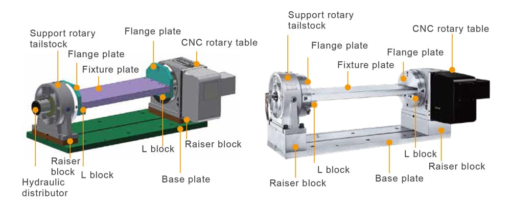
Suggested Dimension of Fixture and Base Plate
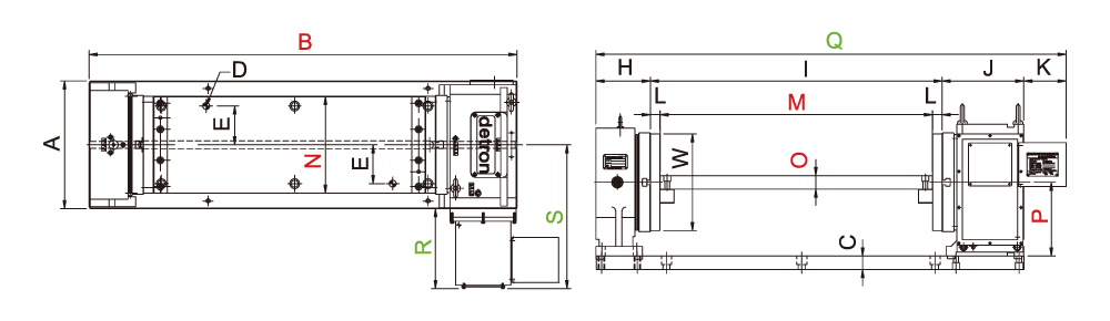
Defined by the number of parts and work pieces.
Below dimension is based on short motor cover. Depending on the motor selection, K, Q, R, and S would have difference. For other motor spec, please refer to detron's outline drawing. Please also take into account interference with the machine tool.
Worm Gear Type Models
unit: mm / inch
| MODEL | Unit | GXA-125S | GXA-170S/H | GXA-210S/H | GXA-255H | GXA-320H | GXA-400H |
|---|---|---|---|---|---|---|---|
| X axis stock | mm / inch | 500 / 20 | 600 / 24 | 700 / 28 | 800 / 32 | 1000 / 40 | 1300 / 51 |
| A | mm/inch | 210 / 8.27 | 270 / 10.63 | 270 / 10.63 | 330 / 12.99 | 360 / 14.17 | 450 / 17.72 |
| B | mm/inch | 726 / 28.58 | 856 / 33.7 | 956 / 37.64 | 1101 / 43.35 | 1241 / 48.86 | 1440 / 56.69 |
| C | mm/inch | 30 / 1.18 | 35 / 1.38 | 35 / 1.38 | 35 / 1.38 | 40 / 1.57 | 40 / 1.57 |
| D | mm/inch | 2-Ø14 / 2-Ø0.55 | 2-Ø18 / 2-Ø0.71 | 2-Ø18 / 2-Ø0.71 | 2-Ø18 / 2-Ø0.71 | 2-Ø18 / 2-Ø0.71 | 2-Ø18 / 2-Ø0.71 |
| E | mm/inch | 80 / 3.15 | 100 / 3.94 | 100 / 3.94 | 100 / 3.94 | 100 / 3.94 | 125 / 4.92 |
| H | mm/inch | 130 / 5.12 | 130 / 5.12 | 130 / 5.12 | 140 / 5.51 | 145 / 5.71 | 190 / 7.48 |
| I | mm/inch | 441 / 17.36 | 551 / 21.69 | 651 / 25.63 | 751 / 29.57 | 861 / 33.90 | 961 / 37.83 |
| J | mm/inch | 155 / 6.10 | 175 / 6.9 | 175 / 6.9 | 210 / 8.27 | 235 / 9.25 | 254.5 / 10.02 |
| K | mm/inch | 89 / 3.5 | 111.5 / 4.4 | 109.5 / 4.3 | 102.6 / 4.04 | 116.5 / 4.58 | 117.5 / 4.63 |
| L | mm/inch | 20 / 0.79 | 25 / 0.98 | 25 / 0.98 | 25 / 0.98 | 30 / 1.18 | 30 / 1.18 |
| M | mm/inch | 400 / 15.75 | 500 / 19.69 | 600 / 23.62 | 700 / 27.56 | 800 / 31.50 | 900 / 35.43 |
| N | mm/inch | 120 / 4.72 | 170 / 6.69 | 200 / 7.87 | 250 / 9.84 | 300 / 11.81 | 400 / 15.75 |
| O | mm/inch | 30 / 1.18 | 30 / 1.18 | 30 / 1.18 | 40 / 1.57 | 40 / 1.57 | 40 / 1.57 |
| P | mm/inch | 110 / 4.33 | 135 / 5.31 | 160 / 6.30 | 190 / 7.48 | 210 / 8.27 | 255 / 10.04 |
| Q | mm/inch | 815 / 32.08 | 967.5 / 38.1 | 1072.5 / 42.2 | 1216 / 47.87 | 1357.5 / 53.4 | 1523 / 60 |
| R | mm/inch | 206 / 8.11 | 190 / 7.48 | 190 / 7.48 | 197 / 7.75 | 236 / 9.29 | 246 / 9.68 |
| S | mm/inch | 311 / 12.24 | 325 / 12.8 | 325 / 12.79 | 362 / 14.25 | 416 / 16.37 | 471 / 18.54 |
| W | mm/inch | 107 / 4.21 | 126 / 4.96 | 141 / 5.55 | 180.5 / 7.10 | 206.5 / 8.12 | 230 / 9.05 |
Remark 1: The center height of permissible error between rotary table and support rotary tailstock is within
Remark 2: Contact detron technical division for proper software adjustment under mass factors of fixture. ± 0.01 mm
Remark 2: Contact detron technical division for proper software adjustment under mass factors of fixture. ± 0.01 mm
Roller Gear Cam Type Models
unit: mm / inch
| MODEL | Unit | RCX-170S/H | RCX-210S/HⅡ | RCX-250ES/HⅡ | RCX-255H | RCX-320H | RCX-400H |
|---|---|---|---|---|---|---|---|
| X axis stock | mm / inch | 600 / 24 | 700 / 28 | 700 / 28 | 800 / 32 | 1000 / 40 | 1300 / 51 |
| A | mm/inch | 270 / 10.6 | 270 / 10.6 | 270 / 10.6 | 330 / 13 | 360 / 14 | 450 / 18 |
| B | mm/inch | 873 / 34 | 979 / 39 | 993 / 39 | 1107.5 / 43.6 | 1241 / 48.86 | 1406 / 55.35 |
| C | mm/inch | 35 / 1.38 | 35 / 1.38 | 35 / 1.38 | 35 / 1.38 | 40 / 1.57 | 40 / 1.57 |
| D | mm/inch | 2-Ø18 / 2-Ø0.71 | 2-Ø18 / 2-Ø0.71 | 2-Ø18 / 2-Ø0.71 | 2-Ø18 / 2-Ø0.71 | 2-Ø18 / 2-Ø0.71 | 2-Ø18 / 2-Ø0.71 |
| E | mm/inch | 100 / 3.94 | 100 / 3.94 | 100 / 3.94 | 100 / 3.94 | 100 / 3.94 | 125 / 4.92 |
| H | mm/inch | 130 / 5.12 | 130 / 5.12 | 130 / 5.12 | 140 / 5.51 | 145 / 5.70 | 190 / 7.48 |
| I | mm/inch | 551 / 21.70 | 651 / 25.6 | 651 / 25.6 | 751 / 29.56 | 861 / 33.90 | 961 / 37.83 |
| J | mm/inch | 192 / 7.56 | 198 / 7.80 | 212 / 8.35 | 216.5 / 8.52 | 235 / 9.25 | 255 / 10 |
| K | mm/inch | 120 / 4.72 | 116 / 4.57 | 116 / 4.57 | 115.5 / 4.55 | 116.5 / 4.59 | 116.5 / 4.59 |
| L | mm/inch | 25 / 0.98 | 25 / 0.98 | 25 / 0.98 | 25 / 0.98 | 30 / 1.18 | 30 / 1.18 |
| M | mm/inch | 500 / 19.69 | 600 / 23.62 | 600 / 23.62 | 700 / 27.56 | 800 / 31.50 | 900 / 35.43 |
| N | mm/inch | 170 / 6.70 | 200 / 7.87 | 200 / 7.87 | 250 / 9.84 | 300 / 11.8 | 400 / 15.75 |
| O | mm/inch | 30 / 1.18 | 30 / 1.18 | 30 / 1.18 | 40 / 1.57 | 40 / 1.57 | 40 / 1.57 |
| P | mm/inch | 135 / 5.31 | 160 / 6.30 | 160 / 6.30 | 190 / 7.48 | 210 / 8.27 | 255 / 10 |
| Q | mm/inch | 993 / 39 | 1095 / 43.11 | 1109 / 43.66 | 1223 / 48 | 1357.5 / 53.44 | 1522.5 / 59.94 |
| R | mm/inch | 218 / 8.58 | 210 / 8.27 | 210 / 8.27 | 272 / 10.7 | 246 / 9.69 | 246 / 9.69 |
| S | mm/inch | 353 / 13.90 | 345 / 13.58 | 345 / 13.58 | 437 / 17.2 | 426 / 16.77 | 471 / 18.54 |
| W | mm/inch | 126 / 4.96 | 141 / 5.55 | 141 / 5.55 | 180.5 / 7.11 | 206.5 / 8.13 | 230 / 9 |
Remark 1: The center height of permissible error between rotary table and support rotary tailstock is within
Remark 2: Contact detron technical division for proper software adjustment under mass factors of fixture. ± 0.01 mm
Remark 2: Contact detron technical division for proper software adjustment under mass factors of fixture. ± 0.01 mm