



- Home
- Blog
- Technical Articles
- Straight and Helical Groove Machining Multi-Axis Synchronization, Toolpath Planning, and Quality Control
Straight and Helical Groove Machining Multi-Axis Synchronization, Toolpath Planning, and Quality Control
In CNC machining, slot features may appear geometrically simple, but they often expose massive differences in machining quality and production efficiency. Straight and helical slots, in particular, demand strict control not only over slot width, depth, and surface finish but also over toolpath planning, cutting parameters, synchronous interpolation between rotary and linear axes, and workpiece clamping rigidity.
By adopting appropriate machining strategies based on workpiece geometry and material characteristics—and by strictly controlling cutting loads and multi-axis kinematics—machinists can drastically improve operational stability. This also directly contributes to reduced tool wear, less frequent tool changes, and lower secondary finishing costs.
1. Machining Characteristics of Straight and Helical Slots
Straight Slot Machining
Straight slots are fundamental machined features. The primary requirements include slot width, depth, bottom profile, wall perpendicularity, and surface roughness.
While the toolpath is relatively straightforward, machining hard materials, deep slots, or narrow slots can still trigger several issues due to excessive tool overhang, extreme cutting loads, or poor chip evacuation. These issues include:
- Cutting chatter (vibration).
- Tool deflection.
- Tool marks on the slot walls.
- Burrs or built-up edge (BUE).
- Dimensional deviations in slot width and depth.
Helical Groove Machining
Helical groove machining usually requires synchronous interpolation between a rotary axis and one or more linear axes. The tool must move along a defined helical curve or lead path while maintaining stable contact with the workpiece.
This type of machining is commonly used for:
- Helical guide grooves
- Tooling and tool holder components
- Hobs and forming tools
- Transmission and guiding components
- Cylindrical workpieces with special functional features
Layered Cutting and Multi-Step Feeding
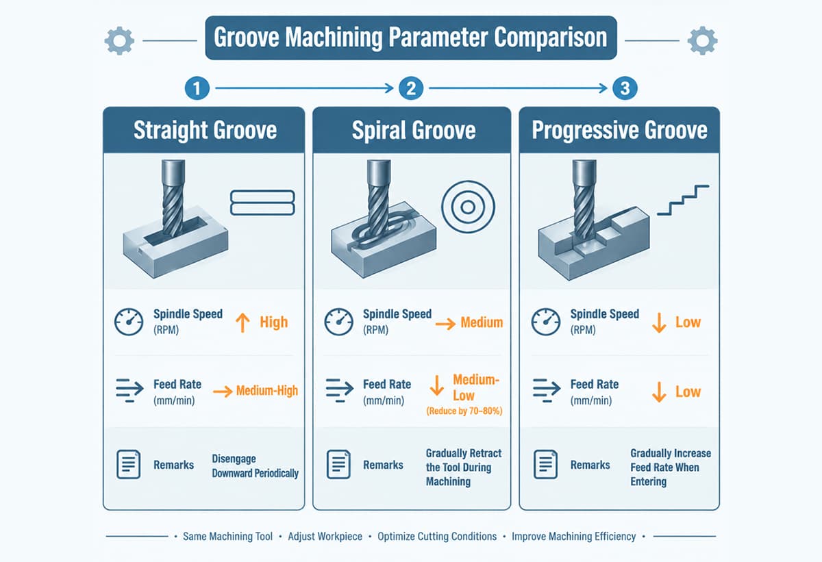
Layered cutting or multi-step feeding is not a separate groove type. It is a machining strategy that can be applied to straight grooves, helical grooves, and deep groove machining.
For deep grooves, long grooves, or workpieces that are not suitable for heavy cutting in one pass, material can be removed gradually in multiple depth levels. This reduces cutting load in each pass and improves process stability.
When combined with helical ramping, ramp entry, or multi-stage finishing, this strategy can also improve chip evacuation, balance tool loading, reduce cutting vibration, and lower the risk of tool breakage.
2. Synchronous Interpolation Between Rotary and Linear Axes
The key to improving groove machining stability is not simply whether the rotary table can rotate. The real challenge is whether the rotary axis and linear axes can move in a synchronized and controlled manner.
In 4-axis machining or 5-axis machining, the rotary axis often needs to coordinate with the X, Y, and Z linear axes. The CNC controller calculates axis position, speed, acceleration, and deceleration according to the machining curve and workpiece coordinate system, allowing the tool to follow the required contour.
Machining quality may be affected by several factors:
- Rotary axis positioning accuracy
- Rotary axis backlash
- Servo following error
- Multi-axis interpolation accuracy
- Acceleration and deceleration settings of linear and rotary axes
- Workpiece clamping rigidity
- Vibration characteristics of the tool and spindle system
Therefore, in helical groove machining or complex contour machining, manufacturers should not only choose the right toolpath, but also confirm the rotary axis positioning performance, low-backlash characteristics, clamping rigidity, and multi-axis interpolation capability of the CNC controller.
3. Cutting Parameters and Toolpath Planning
Cutting parameters should be adjusted according to workpiece material, tool material, tool diameter, groove depth, groove width, machining allowance, and machine rigidity. A fixed spindle speed and feed rate should not be applied to every groove machining process.
Rough Machining
The main purpose of rough machining is stable material removal. During this stage, manufacturers should pay attention to the following points:
- Avoid excessive depth of cut in a single pass
- Control radial and axial cutting loads
- Maintain smooth chip evacuation
- Avoid keeping the tool under high load for too long
- Select proper cooling and lubrication based on material characteristics
- For hard materials or difficult-to-machine alloys, conservative cutting parameters may be necessary to prevent tool chipping, vibration, or sudden tool failure.
Finish Machining
Finish machining should focus on dimensional stability, contour accuracy, and surface roughness. The following practices can help improve final machining quality:
- Leave uniform and appropriate finishing allowance
- Reduce finishing depth of cut and radial engagement
- Use stable lead-in, lead-out, and exit paths
- Avoid sudden cutting load changes at corners or local features
- Ensure sufficient dynamic stability of the tool, tool holder, and spindle system
For deep grooves or long grooves, layered cutting, multi-step feeding, or helical ramping is recommended to reduce cutting force and vibration.
4. Tool Wear and Chip Evacuation Management
Common cost issues in groove machining include rapid tool wear, cutting edge chipping, poor chip evacuation, and excessive machining time.
When cutting load is uneven, tool overhang is too long, or chips cannot be removed smoothly, the cutting edge may wear quickly. This can lead to built-up edge, scratched groove walls, dimensional variation, and unstable surface finish.
For deep groove and narrow groove machining, chip evacuation is especially important. When necessary, high-pressure coolant, proper tool retraction, pecking strategies, or segmented cutting can be used to prevent chip re-cutting.
By optimizing the rotary axis angle and toolpath strategy, manufacturers can improve cutting contact conditions between the tool and workpiece. This helps reduce local overload and cutting vibration, which may extend tool life and improve machining consistency.
For mass production, tool cost should not be evaluated only by the price of a single cutting tool. A more complete cost analysis should include:
- Cycle time per part
- Tool life
- Tool change frequency
- Tool adjustment time
- Defect rate
- Surface quality variation caused by tool wear
5. Surface Roughness and Machining Stability
Groove surface quality often directly affects the assembly, sliding, sealing, guiding, or transmission function of the part. Therefore, surface roughness should not be judged only by visual inspection. It should be controlled according to drawing requirements and actual functional needs.
Factors that influence groove surface quality include:
- Cutting edge condition
- Tool runout
- Spindle and tool holder rigidity
- Cutting speed and feed rate
- Finishing allowance
- Toolpath and lead-in / lead-out strategy
- Cooling and lubrication conditions
- Workpiece clamping and machine vibration
During finish machining, a uniform allowance should be maintained before the final pass, and the final depth of cut should not be excessive. Tool motion should also remain smooth, especially near corners or transition areas, to reduce speed changes, tool marks, and accumulated surface defects.
6. Inspection of Dimensional, Profile, and Geometric Accuracy
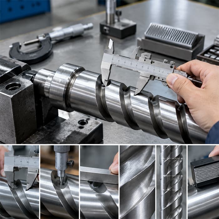
After groove machining is completed, inspection should be carried out according to the part drawing, technical specifications, and inspection plan. Key inspection items include:
- Groove width and groove depth
- Groove bottom shape and corner radius
- Groove wall perpendicularity or profile
- Groove position and direction
- Burrs, scratches, or abnormal tool marks on groove walls
- Pitch, lead, and helix angle of helical grooves
- Surface roughness
- Dimensional tolerance and geometric tolerance specified on the drawing
Groove Width and Groove Depth
The acceptance criteria for groove width and groove depth should be based on the part drawing and functional requirements. A single tolerance value should not be applied to all groove machining applications.
Depending on groove type, size, and precision requirements, the following measuring tools may be used:
- Pin gauges or plug gauges
- Depth gauges
- Internal measuring instruments
- Dedicated groove width gauges
- Vision measuring systems
- Coordinate measuring machines, also known as CMMs
For example, a precision mating component may require a tolerance of ±0.02 mm or tighter. However, the actual tolerance should always follow the engineering drawing, customer specifications, and inspection standards.
Helical Groove Pitch and Profile
A helical groove can be inspected using a CMM, dedicated profile measuring equipment, or another suitable measuring system. Important inspection items include:
- Helical pitch or lead
- Helix angle
- Groove profile
- Groove width and groove depth
- Groove position and direction
- Profile deviation caused by rotary and linear axis interpolation
If pitch or profile errors are found, further analysis should be conducted. Possible causes include rotary axis positioning error, backlash, servo following error, multi-axis synchronization error, and tool wear. The problem should not be attributed only to rotary axis backlash without detailed evaluation.
Geometric Tolerances
If the engineering drawing includes GD&T requirements, inspection should follow the specified geometric dimensioning and tolerancing standards. Items may include position, orientation, parallelism, perpendicularity, profile, or symmetry.
The groove bottom radius, groove wall profile, and center position should be evaluated according to the actual function of the part and the drawing specifications.
7. Reliable Multi-Axis Machining Support for Groove Applications
Straight grooves and helical grooves may appear to be simple groove features. In actual machining, however, they require balanced control of toolpath planning, cutting parameters, chip evacuation, tool life, workpiece clamping, and multi-axis synchronization.
For complex groove features and multi-axis machining, rotary axis positioning accuracy, low-backlash transmission, structural rigidity, and clamping performance directly affect machining quality, dimensional consistency, and production efficiency.
Detron Machine Co., Ltd. focuses on high-precision CNC 4th-axis and 5th-axis rotary tables. With stable rotary positioning, low-backlash transmission, high-rigidity structure, and reliable clamping performance, Detron provides strong multi-axis machining support for milling machines.
For manufacturers working on straight groove machining, helical groove machining, deep groove machining, or complex CNC slot machining, Detron rotary tables help improve machining stability, repeat positioning accuracy, and overall production efficiency.